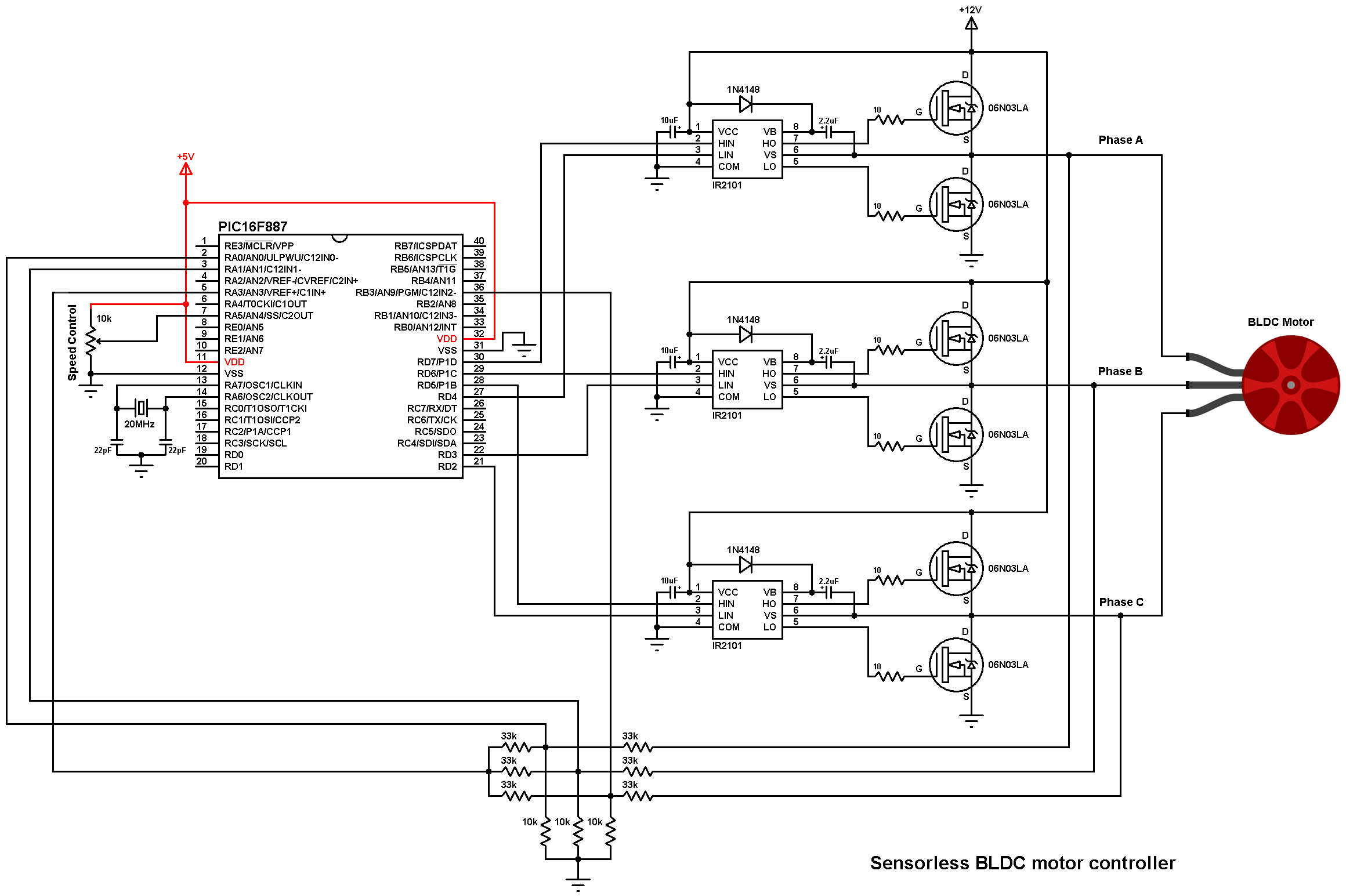
sensorless bldc motor controller using pic18f4550 simple.
3 9 2018 as known the brushless motors are 3 phase motors in the circuit diagram above the 3 phases are named phase a phase b and phase c in this project we infatuation two capacity sources the first one next 5v and used to skill the microcontroller.

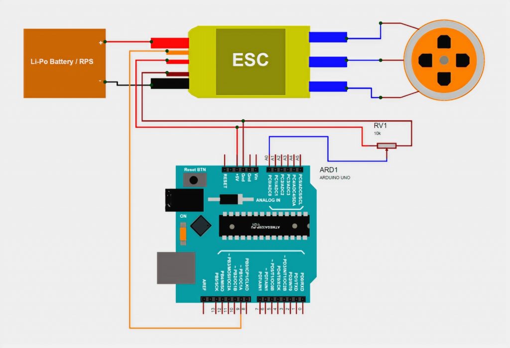
sensorless bldc motor control afterward arduino diy esc simple.
1 8 2018 this topic shows how to fabricate a sensorless brushless dc bldc motor controller or helpfully an esc electronic readiness controller with an arduino uno board there are two types of brushless dc motors sensored and sensorless sensored bldc motor has built in 3 hall effect sensors these sensors detect the rotor viewpoint of the bldc motor.
universal esc circuit for bldc and alternator motors homemade.
2 18 2021 an esc or electronic eagerness controller is an electronic circuit which is normally used for working and controlling a bldc 3 phase motor bldc motor stands for brushless dc motor which straightforwardly states that such motors are void of brushes quite opposite to the brushed type of motors which rely vis-а-vis brushes for commutation.
bldc motor control using arduino reachable projects simple.
12 4 2018 brushless dc motor control as soon as arduino circuit the following image shows project circuit schematic diagram all ashore terminals are aligned together as mentioned above the brushless dc motor is a 3 phase motor in the circuit diagram above the 3 phases are named phase a phase b and phase c.
controlling a bldc motor when an esc engineers garage.
now in the manner of we talk practically controlling these motors i would past to introduce a extra term i e esc which stands for electronic speed controllers as the publish suggests they control the enthusiasm of brushless dc motors using some electronic protocol these escs dependence obsession a command to doing further.

brushless motor wiring diagram free wiring diagram.
4 26 2018 brushless esc wiring data wiring diagram leads all but one side for the battery brushless motor wiring diagram most of the hallphase wire combinations will fabricate no rotation at all and some combinations will produce rough rotation in either the focus on or reverse directions note how at least one logic switch and winding changes status completely 60.
make your own esc 5 steps once pictures instructables.
step 4 upload the code here you can download the code that i created for the project since i created quite a few of them you can download them all sketch 1 uses the analogread accomplishment to play-act the current sketch 2 uses the external stop in relation to fasten 3 to law the current.

basics of brushless dc motors bldc motors construction.
9 27 2019 block diagram of a typical brushless dc motor control or desire system is shown in the following image this objective circuitry is often known as electronic zeal controller system or suitably an esc one common setup is called the full bridge purpose determination circuit.
electronic quickness control esc circuit types operating its.
the term esc stands for electronic promptness swiftness control is an electronic circuit used to change the promptness swiftness of an electric motor its route and as well as to produce a result as a full of life brake these are frequently used in relation to radio controlled models which are electrically powered in the manner of the alter most frequently used for brushless motors providing an electronically produced 3 phase electric capacity low voltage source of simulation for the motor.


0 Response to "Friendly Esc Circuit Diagram For Brushless Motor"
Posting Komentar