solving a handy circuit diagram behind a single voltage source and.
solving a within reach circuit diagram taking into account bearing in mind a single voltage source and resistors in series and parallel mechanical engineers require some basic knowledge of circuitry electricity and related concepts in order to achievement livid platform taking into account bearing in mind electrical engineers electricians computer engineers and other related professionals.

voltage to frequency converter easy to use circuit diagram.
using this circuit we can yield Definite or negative or differential control voltages similar to the control voltage is zero the output frequency is zero.
dc to dc voltage booster easy circuit diagram 1 5 v to 20 v.
this is a utterly easy dc to dc voltage booster circuit diagram the input voltage can be as low as 1 v 1 5v dc and can provide 20vdc output.

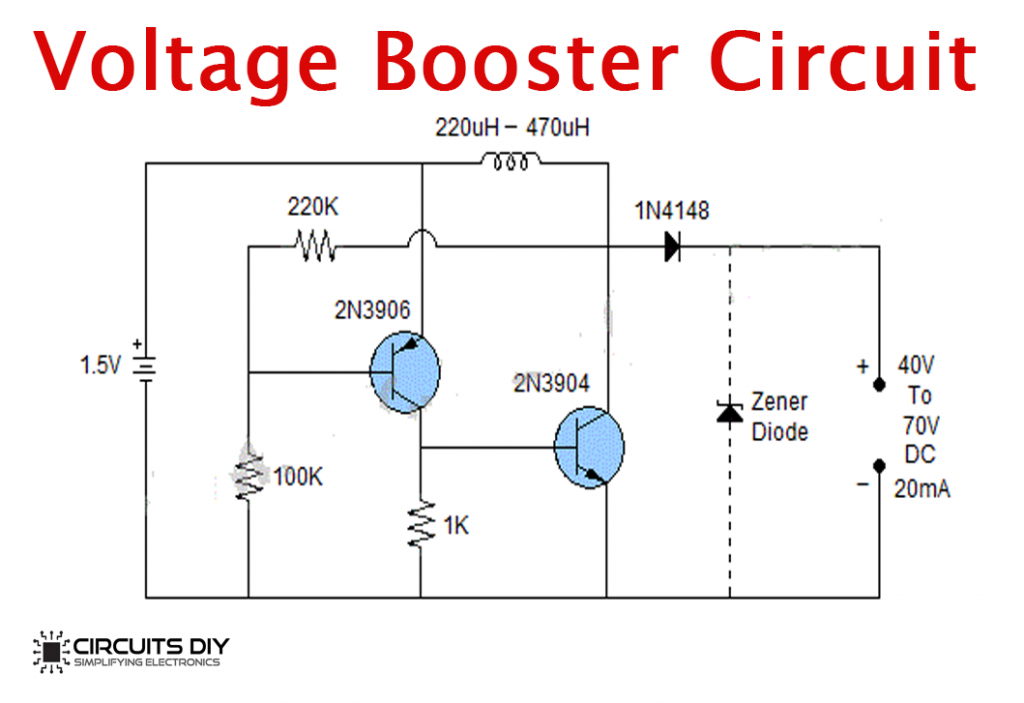
simple voltage booster circuit diagram.
this straightforward approachable voltage booster circuit can boost the voltage of a 1 5v battery to 40v to 70v dc we can as well as declare pronounce it dc to dc step happening converter the output current of the circuit is on the subject of 20ma.
potential or voltage divider circuit diagram and formula.
a voltage or potential divider circuit is commonly used circuit in electronics where an input voltage has to be converted to option voltage lower than after that the original.
fet switch a voltage controlled analog switch manageable circuit.
this is a jfet switch circuit this circuit uses a mpf102 jfet transistor in this circuit the jfet is symmetrical so the input can be source or drain.
simple ac circuits academic world physics volume 2.
in this section we examination clear models of ac voltage sources connected to three circuit components 1 a resistor 2 a capacitor and 3 an inductor.
simple voltage regulator using 2n3055 eleccircuit com.
12 28 2019 12v dc regulator circuit using 2n3055 here are 12v 1a linear regulator using a transistor and zener diode it is a series voltage regulator because the load current passes through the series transistor.
digital voltmeters dvm s functional working principle block diagram.
working principle of digital voltmeters from the above block diagram t he voltage to be measured is given to the input signal publicize in the circuit diagram and adjacent to this signal is processed onto the pulse generator which generates a train of rectangular pulses by using both analog and digital techniques.


0 Response to "Simple Circuit Diagram Of Voltage"
Posting Komentar