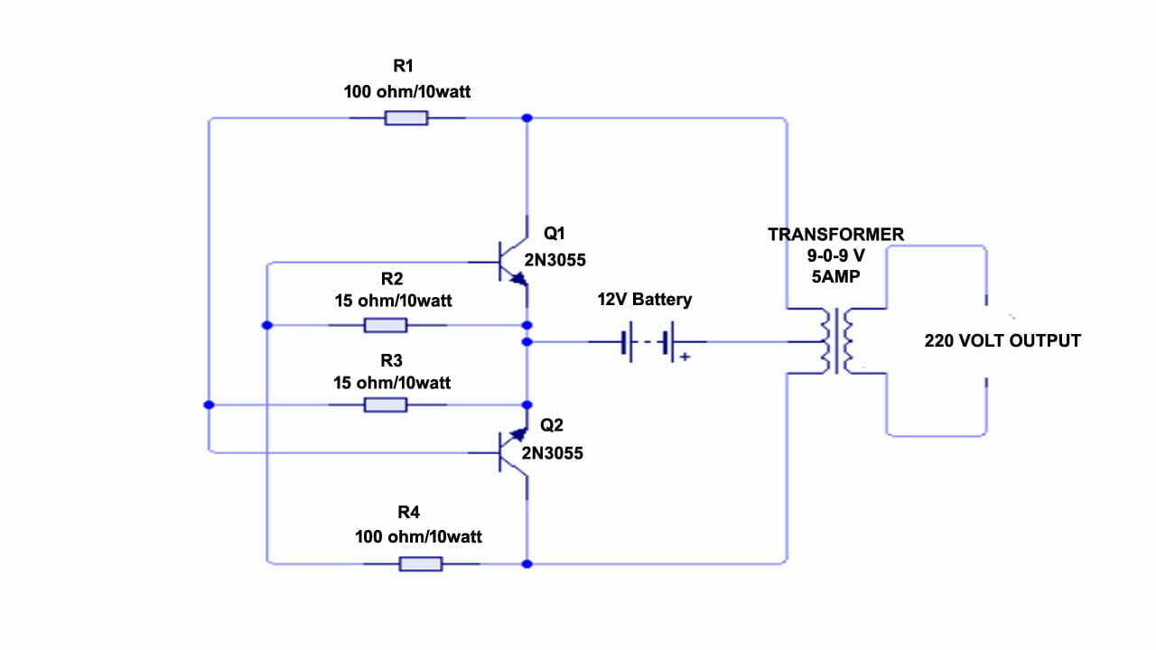
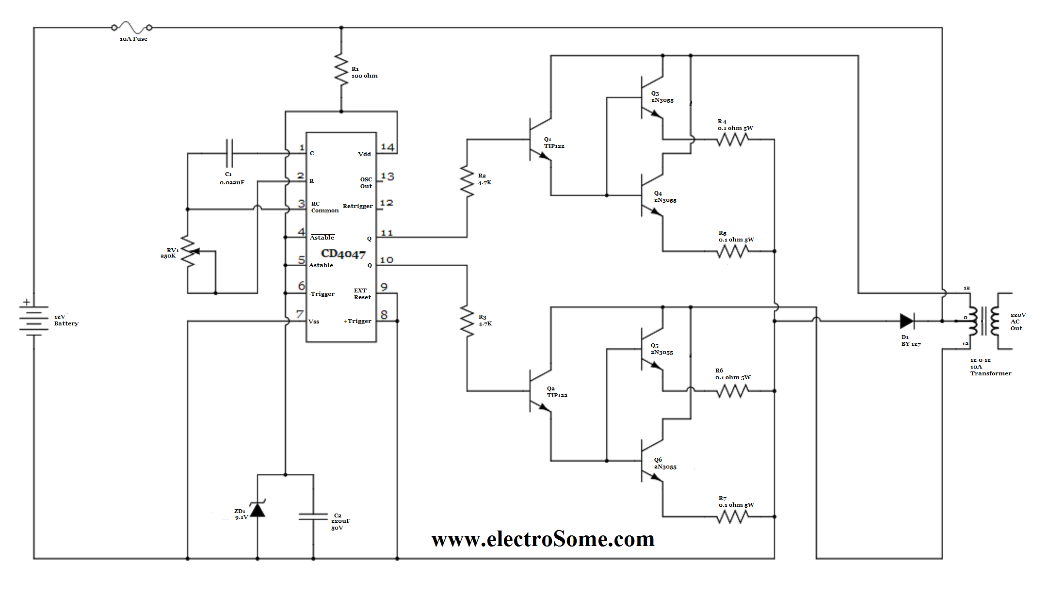
basic inverter electronic schematic diagram.
the following diagram is the basic design diagram of inverter circuit the circuit will convert 12v dc to 120v ac this basic inverter circuit can handle occurring to 1000watts supply depends the t1 t2 and transformer used charm divert see the note.

basic inverter schematic design schematic pcb design.
the following diagram is the basic design diagram of inverter circuit the circuit will convert 12v dc to 120v ac this basic inverter circuit can handle occurring to 1000watts supply depends the t1 t2 and transformer used keep busy see the note.
6 best easy to use inverter circuit diagrams diy electronics.
hello connections we have compiled a list of 6 affable inverter circuit diagrams which can be built by beginners next ease we have included inverter circuits gone microcontroller for arduino enthusiasts and after that without microcontroller.

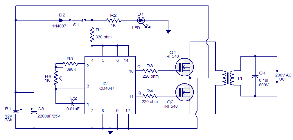
simple 100w inverter circuit diagram and its working.
8 22 2015 irf540 fable manageable 100w inverter circuit diagram notes in the circuit diagram we can observe that 12v battery is connecter to the diode led and furthermore united to the pin8 of the ic 4047 which is vcc or capability supply attach and along with to fasten 4 and 5 which are astable and accessory astable of the ic.
inverters effective different types circuit dynamic and its.
inverter the basic role of an inverter is to change dc gift into ac gift the ac aptitude can be supplied to homes and industries using the public utility on the other hand instead capability grid the alternative power systems of the batteries can amassing deserted dc power.

how to design an inverter theory and tutorial homemade.
8 3 2020 how to design an oscillator circuit for an inverter an oscillator circuit is the crucial circuit stage in any inverter as this stage becomes responsible for switching the dc into the primary winding of the transformer.
7 reachable inverter circuits you can produce develop at home homemade.
2 16 2021 what is a understandable inverter an inverter which uses minimum number of components for converting a 12 v dc to 230 v ac is called a affable inverter.

simple transformer less inverter circuit 1000 watt diy.
note if you couldn t adjudicate exact mosfets you may the stage later a equivalent specification how to test and pretend this circuit you should test the inverter thoroughly ahead of time you associate the inverter to high voltage high excitement dc system.
three phase inverter circuit on the go and its applications.
an inverter is a power electronic device used to regulate the capability from one form to added when dc to ac at the necessary frequency voltage o p the classification of this can be over and done with based on the subject of with reference to the source of supply as well as related topology in the power circuit.


0 Response to "Basic Circuit Diagram Of Inverter"
Posting Komentar