

the refrigeration cycle explained in plain english. the metering device component 3 on this refrigeration cycle diagram is the dividing point between the high pressure and low pressure sides of the system and is designed to maintain a specific rate of flow of refrigerant into the low side of the system.
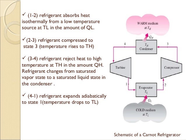
heat pump and refrigeration cycle wikipedia. the vapor compression cycle is used in most household refrigerators as well as in many large commercial and industrial refrigeration systems figure 1 provides a schematic diagram of the components of a typical vapor compression refrigeration system. simple vapour compression refrigeration system with. a simple vapour compression system of refrigeration consists of the equipment as follows a compressor advertisements b condenser c expansion valve d evaporator the schematic diagram of the arrangement is shown in fig 36 20 the low temperature low pressure vapour at state b is compressed by the compressor. images of schematic diagram refrigeration system. lets add a basic control system to a refrigeration system first we need to know what loads there are to be controlled the image on the left shows a small split system for a walk in cooler with 3 electrical devices a compressor condenser fan motor and evaporator fan motor. refrigeration basics controls. the schematic diagram of a single stage refrigeration system shown in figure 1 does not include other equipment items that would be provided in a large commercial or industrial vapor compression refrigeration system such as. vapor compression refrigeration wikipedia. figure 10 carnot refrigeration cycle a schematic diagram and b t s diagram a refrigeration system is a combination of components and equipment connected in a sequential order to produce the desired refrigeration effect cooling or heating.
engineering design guideline refrigeration systems rev02. 26 02 2014 discuss temperature entropy ts and pressure enthalpy ph property diagrams for vapor compression refrigeration system. property diagrams ts and ph for refrigeration 2 youtube. 21 06 2010 this dvd is a compilation of the following titles refrigeration air conditioning fuse ratings the good earth basic electrical effects ohms law series parallel circuits wiring diagrams. wiring diagrams circuits refrigeration air. yeah it seems complicated at first but it will be easier to understand once i explain the refrigeration cycle diagram section by section it is important to understand the basic refrigeration cycle it help us to comprehend what is going on within the air conditioner units. basic refrigeration cycle. refrigeration system pipes are sized to offer a low resistance to flow flow diagram for single cycle refrigeration system the resulted refrigeration schematic proves to be efficient in utilizing the available refrigerant to satisfy all process heating cooling demands. refrigeration system an overview sciencedirect topics.
schematic arduino uno,schematic adalah,schematic arduino nano,schematic advan e1c 3g,schematic acer e5-411,schematic arduino uno r3,schematic asus x014d,schematic asus z00ad,schematic acer z1401,schematic asus x453ma rev 2.0,diagram alir,diagram alir penelitian,diagram adalah,diagram activity,diagram alir adalah,diagram alir proses,diagram aktivitas,diagram alir proses produksi,diagram analisis swot,diagram alir data,refrigeration and air conditioning,refrigeration and air conditioning technology,refrigeration and air conditioning pdf,refrigeration and air conditioning technology 8th edition,refrigeration and air conditioning book,refrigeration and air conditioning jobs,refrigeration and air conditioning notes,refrigeration apprenticeship,refrigeration and air conditioning by cp arora pdf,refrigeration and air conditioning mechanic,system analyst,system adalah,system architecture,system analyst adalah,system administrator,system app remover,system administrator adalah,system analysis,system architecture diagram,system app remover pro
0 Response to "Schematic Diagram Refrigeration System"
Posting Komentar