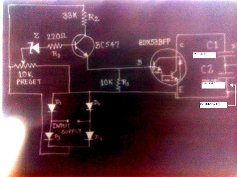

how to use relay with schematic of relay circuit diagram. 21 06 2016 basic schematic circuit diagram of relay the following schematic shows the basic circuit connect the relay with hc11 port pins this is used to control on switches the transistor allows the hc11 to control the medium sized coil current of relay the diode prevents relay from arcing by giving a return path for the energy stored in the magnetic.
relay circuits relay circuit diagram and operation. when analyzing the operation of a relay control system it is helpful to have some way to temporarily denote the conductive status of switch contacts and the energization status of relay coils i e a notation we might sketch using pencil on a diagram to help us follow the operation of the circuit. relay logic wikipedia. the schematic diagrams for relay logic circuits are often called line diagrams because the inputs and outputs are essentially drawn in a series of lines a relay logic circuit is an electrical network consisting of lines or rungs in which each line or rung must have continuity to enable the output device a typical circuit consists of a number of rungs with each rung controlling an output this output is controlled by a combination of input or output conditions such as input switches and control relays the conditions that r. images of relay circuit schematic diagram. npn darlington relay switch circuit the previous npn transistor relay switch circuit is ideal for switching small loads such as led s and miniature relays but sometimes it is required to switch larger relay coils or currents beyond the range of a bc109 general purpose transistor and this can be achieved using darlington transistors. relay switch circuit and relay switching circuit. wiring diagram book a1 15 b1 b2 16 18 b3 a2 b1 b3 15 supply voltage 16 18 l m h 2 levels b2 l1 f u 1 460 v f u 2 l2 l3 gnd h1 h3 h2 h4 f u 3 x1a f u 4 f u 5 x2a r l3 circuit breaker stop start m ot t1 t2 t3 m m solid state overload relay 1ct m m motor 3ct to 120 v separate nema and iec markings and schematic diagrams 4 control and. wiring diagram book schneider electric. thus the current flow through it will also be very high to reduce this the value of the resistance should be as high as 1 kilo ohm but as the value of the resistors increases the voltage spiking capability of the relay decreases take a look at the circuit diagram below to understand more de spiking resistor relays types of relays.
relays circuit wiring diagrams. this first schematic is a circuit where the set switch has priority this means that if both the set and reset switches are pressed at the same time the relay will turn on the next schematic shows a circuit where the reset switch has priority if the set and reset switches are pressed simultaneously the relay will turn off. latching relay circuit schematic azatrax com. relays are switches that open and close circuits electromechanically or electronically relays control one electrical circuit by opening and closing contacts in another circuit as relay diagrams show when a relay contact is normally open no there is an open contact when the relay is not energized. how relays work relay diagrams relay definitions and. 11 06 2016 relay switch circuit diagram working of the basic 5v relay circuit in the above circuit 5v relay is powered by a 9v battery an on off switch is added for the switching purpose of the relay at the initial condition when switch is open no current flow through coil hence common port of relay is connected to no normally open pin so the. simple relay switch circuit diagram. 14 01 2016 the first circuit to be discussed is a basic control circuit used throughout industry figure 9 14 shows a start stop push button circuit this schematic shows both the control circuit and the motor circuit schematic diagrams do not always show both control and motor connections many schematic diagrams show only the control circuit. control circuits schematic diagrams wiring diagrams.
relay adalah,relay arduino,relay ac,relay artinya,relay ac mobil,relay adalah pdf,relay access denied,relay arus lebih,relay arduino adalah,relay arduino code,circuit adalah,circuit analysis,cricut australia,cricut alternative,circuit app,circuit arcade bar,cricut air 2,circuit apartments,circuit analyzer,circuit abbreviation,schematic arduino uno,schematic adalah,schematic arduino nano,schematic advan e1c 3g,schematic acer e5-411,schematic arduino uno r3,schematic asus x014d,schematic asus z00ad,schematic acer z1401,schematic asus x453ma rev 2.0,diagram alir,diagram alir penelitian,diagram adalah,diagram activity,diagram alir adalah,diagram alir proses,diagram aktivitas,diagram alir proses produksi,diagram analisis swot,diagram alir data
0 Response to "Relay Circuit Schematic Diagram"
Posting Komentar