


plc programmable logic control block diagram input. plc block diagram the central processing unit is the heart of the plc system the cpu is a microprocessor based control system that replaces central relays counters timers and sequencers a processor appears only once in a plc and it can be either a one bit or a word processor one bit processors are adequate for dealing with logic operations.
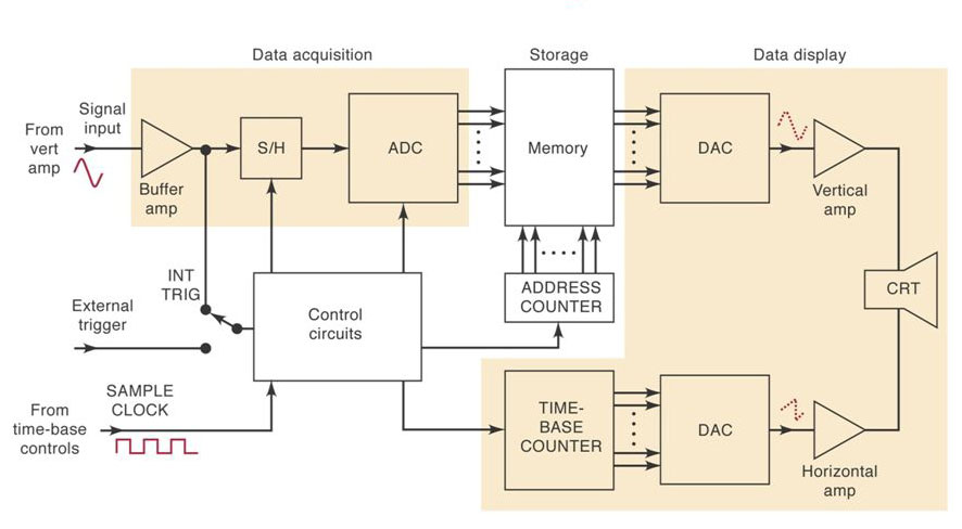
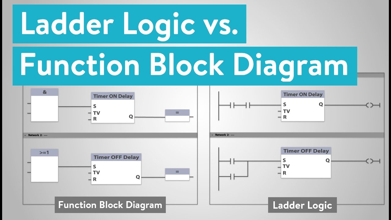
function block diagram fbd programming tutorial plc. the block diagram of programming logic controller plc is shown in above figure the plc has following basic sections are processor section cpu the processor section is brain of plc which consists of ram rom logic solver and user memory. block diagram of programmable logic controller plc. the term function block diagram fbd is used for plc programs described in terms of graphical blocks it is described as a graphical language for depicting signal and data flows through blocks which are reusable software elements a function block is a program instruction unit that when executed yields one or more output values thus a block is represented in the manner shown in figure 5. images of block diagram for plc. plc block diagram you will understand the working principle of plc from the block diagram of plc plc stands for programmable logic controller nowadays plc becomes more and more popular in industries for automation purpose. function block diagram an overview sciencedirect topics. a simplified block diagram of a plc shown in above fig it has three major units sections i o input output modules cpu central processing units programmer monitor the input section converts the field signals supplied by input devices sensors to logic level signals that the plc. explained plc block diagram programmable logic. 09 08 2018 programmable logic controller cro block diagram and working cathode ray oscilloscope cathode ray tube crt structure working duration 13 49 engineering made easy recommended for you.
plc solutions block diagram of plc. the function block diagram fbd is a graphical language for programmable logic controller design that can describe the function between input variables and output variables a function is described as a set of elementary blocks input and output variables are connected to blocks by connection lines inputs and outputs of the blocks are wired together with connection lines or links single lines may be used to connect two logical points of the diagram is. block diag of plc youtube. function block diagram wikipedia. related searches for block diagram for plc.
block ads,block adalah,block ads chrome,block app in firewall,block autocad,block artinya,block ads chrome android,block and tackle,block ads youtube,block all incoming calls android,diagram alir,diagram alir penelitian,diagram adalah,diagram activity,diagram alir adalah,diagram alir proses,diagram aktivitas,diagram alir proses produksi,diagram analisis swot,diagram alir data,for all mankind,for a while,for artinya,for a few dollars more,for all mankind imdb,for a minute,for all the things,for a minute lyrics,for arduino,for all we know lyrics,plc adalah,plc allen bradley,plc arduino,plc adalah pdf,plc abb,plc analog input,plc apa itu,plc acronym,plc apoteker,plc analog input scaling formula

0 Response to "Block Diagram For Plc"
Posting Komentar