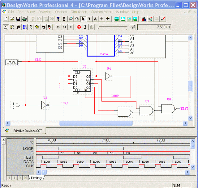


circuitverse online digital logic circuit simulator. explore digital logic circuits with from simple gates to complex sequential circuits plot timing diagrams automatic circuit generation explore standard ics and much more for free.
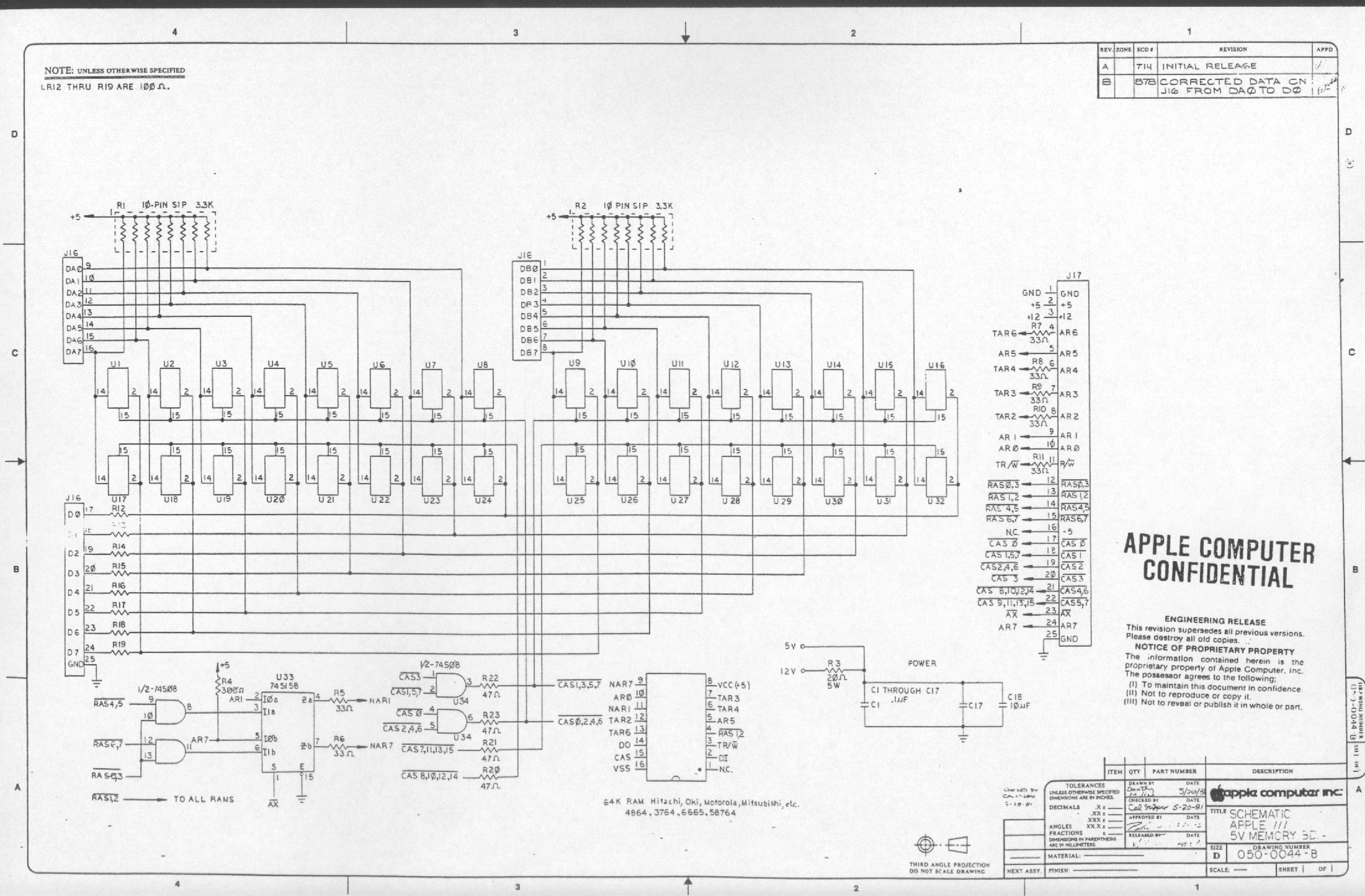
difference between schematics and circuit diagrams. circuit diagram a circuit diagram also named electrical diagram elementary diagram electronic schematic is a graphical representation of an electrical circuit circuit diagrams are widely used for the circuit design construction and maintenance of electrical and electronic equipment. logic gate wikipedia. in electronics a not gate is more commonly called an inverter the circle on the symbol is called a bubble and is used in logic diagrams to indicate a logic negation between the external logic state and the internal logic state 1 to 0 or vice versa on a circuit diagram it must be accompanied by a statement asserting that the positive logic convention or negative logic convention is being. visual walkthrough of schematic diagram and control logic. 05 06 2015 schematic diagrams with graphical symbols are used to show the electrical connections and functions of a specific circuit learn how to explain each component in regards to controlling logic see. logic gate software logic gate tool create logic gates. creately logic circuit generator offers a wide variety of unique features to draw logic gate diagrams swiftly for example cut down hours of time it takes to drag drop and manually connect shapes with our 1 click create and connect function our smart shapes and connectors automatically adjust according to the diagram so you don t have to manually rearrange things as soon as you change a. circuit diagram wikipedia. it is a usual although not universal convention that schematic drawings are organized on the page from left to right and top to bottom in the same sequence as the flow of the main signal or power path for example a schematic for a radio receiver might start with the antenna input at the left of the page and end with the loudspeaker at the right positive power supply connections for each stage would be shown towards the top of the page with grounds negative supplies or other return paths towards the bottom.
relay logic wikipedia. the schematic diagrams for relay logic circuits are often called line diagrams because the inputs and outputs are essentially drawn in a series of lines a relay logic circuit is an electrical network consisting of lines or rungs in which each line or rung must have continuity to enable the output device a typical circuit consists of a number of rungs with each rung controlling an output. digital electronics logic gates basics tutorial circuit. 14 08 2018 an x or gate is a two input one output logic circuit x or gate assumes logic 1 state when any of its two inputs assumes a logic 1 state when both the inputs assume the logic 0 state or when both the inputs assume the logic 1 state the output assumes a logic 0 state the output of the x or gate will be the sum of the modulo sum of its inputs. circuit diagram a circuit diagram maker. circuit diagram is a free application for making electronic circuit diagrams and exporting them as images design circuits online in your browser or using the desktop application. schemeit free online schematic drawing tool digikey. scheme it is a free online schematic drawing tool that will allow you to produce professional looking schematic diagrams add corresponding part numbers and share your schematic with others we have new features read about them in our what s new page under help got it.
schematic arduino uno,schematic adalah,schematic arduino nano,schematic advan e1c 3g,schematic acer e5-411,schematic arduino uno r3,schematic asus x014d,schematic asus z00ad,schematic acer z1401,schematic asus x453ma rev 2.0,diagram alir,diagram alir penelitian,diagram adalah,diagram activity,diagram alir adalah,diagram alir proses,diagram aktivitas,diagram alir proses produksi,diagram analisis swot,diagram alir data,for all mankind,for a while,for artinya,for a few dollars more,for all mankind imdb,for a minute,for all the things,for a minute lyrics,for arduino,for all we know lyrics,logic adalah,logic analyzer,logic algoritma,logic album,logic apps,logic artinya,logic and,logic alessia cara lyrics,logic and eminem,logic and computer design fundamentals,circuit adalah,circuit analysis,cricut australia,cricut alternative,circuit app,circuit arcade bar,cricut air 2,circuit apartments,circuit analyzer,circuit abbreviation
0 Response to "Schematic Diagram For Logic Circuit"
Posting Komentar