

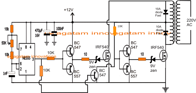


5kva ferrite core inverter circuit full working diagram. a simple ferrite cote inverter design before we learn the 5kva version here s a simpler circuit design for the newcomers this circuit does not employ any specialized driver ic rather works with only n channel mosfets and a bootstrapping stage the complete circuit diagram can be witnessed below.
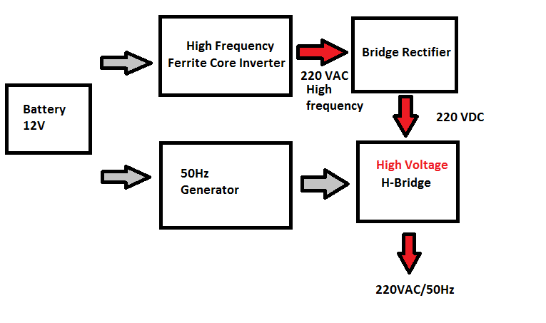
ferrite core inverter circuit diagram diy electronics. full circuit diagram ferrite core inverter circuit exploring different stages of inverter brief what is ferrite core transformer inverter ferrite core inverter is a type of power inverter used for power backup it uses ferrite core transformer to step up the low voltage ac to high voltage ac at high frequencies derived from a dc source. simple transformer less inverter circuit 1000 watt diy. block diagram of transformer less inverter circuit transformerless inverter block diagram dc power source the power source battery bank consists of 12v 7ah 19 batteries connected in series with high voltage mosfets the ferrite core based inverters are also touted as transformerless inverters and their efficiency are also. images of ferrite inverter circuit diagram. the internet is flooded with single phase inverter circuit diagrams but there are only few circuit diagrams of 3 phase inverter out there a simplest possible 3 phase inverter is described here three phase inverters require microcontroller design where the timings of the all three phases need to be precisely timed and executed circuit diagram. 6 best simple inverter circuit diagrams diy. 13 03 2019 the sinewave generator circuit the below given diagram shows a simple sine wave generator circuit which may be used for driving the above inverter circuit however since the output from this generator is exponential by nature might cause a lot of heating of the mosfets. make this 1kva 1000 watts pure sine wave inverter circuit. 05 07 2014 5kva ferrite core inverter circuit in this post we discuss the construction of a 5000 watt inverter circuit which incorporates a ferrite core transformer and therefore is hugely compact than the conventional iron core counterparts.
5kva ferrite core inverter circuit circuit diagram centre. 01 08 2019 looking at the below shown solar based transformerless inverter circuit diagram we can see that it basically consists of three main stages viz the oscillator stage made up of the versatile ic 555 the output stage consisting of a couple of high voltage power mosfets and the power delivering stage which employs the solar panel bank which is. 3 best transformerless inverter circuits homemade. in this post we ll discuss 5 outstanding ic 555 inverter circuits from a simple square wave variant to slightly more advanced spwm sinewave designs and finally a full fledged ferrite core based dc to dc pwm inverter circuit let s begin the idea was requested by mr ningrat edan. 6 best ic 555 inverter circuits explored homemade. few days ago gohz made a 24v 2000w power inverter in home sharing some design schematics and circuit diagrams power inverter testing the picture was taken in short circuited output waveform the spwm accuracy of eg8010 was not high enough waveform so the inverter output was not good enough as pure sine wave the dead zone time was a bit. homemade 2000w power inverter with circuit diagrams gohz com. 500 watt inverter circuit with battery charger how to calculate ferrite core transformers arduino 3 phase inverter circuit with code how to calculate modified sine waveform convert audio amplifier into pure sinewave inverter 7 modified sine wave inverter circuits explored 100w to 3kva. homemade circuits com best electronic projects.
ferrite adalah,ferrite antenna,ferrite and pearlite,ferrite app,ferrite and cementite,ferret animal,ferrite armor,ferrite and austenite,ferrite application,ferrite alpha,inverter adalah,inverter ac,inverter ac adalah,inverter aki,inverter ac to dc,inverter abb,inverter ac ke dc,inverter artinya,inverter aki motor,inverter ac ke ac,circuit adalah,circuit analysis,cricut australia,cricut alternative,circuit app,circuit arcade bar,cricut air 2,circuit apartments,circuit analyzer,circuit abbreviation,diagram alir,diagram alir penelitian,diagram adalah,diagram activity,diagram alir adalah,diagram alir proses,diagram aktivitas,diagram alir proses produksi,diagram analisis swot,diagram alir data

0 Response to "Ferrite Inverter Circuit Diagram"
Posting Komentar