

pdf pcb thermal design improvement through thermal vias. an approach based on design of different experiments for improvement the thermal paths in pcb through thermal vias is offered an efficient thermal via placed on the pcb decreases the junction.
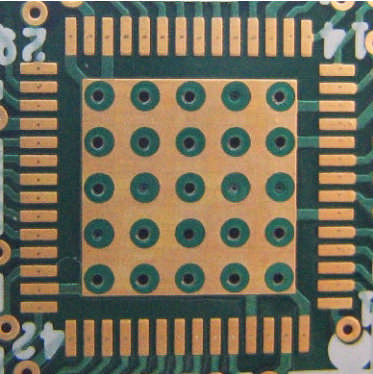
placement of thermal vias basic knowledge rohm tech. placement of thermal vias from this point we explain actual layout examples the following diagram is an example of the layout and dimensions of thermal vias for an htsop j8 package a package type in which a heat dissipating plate is exposed on the bottom surface. pcb thermal design improvement through thermal vias. the effect of the pcb board design on the thermal resistance ja in detail the idea of using thermal vias to solve thermal problems is not new 1 the use of thermal vias in packaging is implemented by two different methods the first one is that the one end of via is attached to the bottom substrate and the other is attached to the top. via electronics wikipedia. pcb via current capacity chart showing 1mil plating via current capacity resistance vs diameter on a 1 6mm pcb in printed circuit board design a via consists of two pads in corresponding positions on different layers of the board that are electrically connected by a hole through the board. how to model thermal vias in your pcb design. learn how to model thermal vias accurately and quickly to suit different design phases using electronics cooling simulation software simcenter flotherm xt a presented simulation study will address options benefits and limitations of thermal vias on a pcb design in relation to other design factors attend this webinar and learn. pcb how closely should i space my thermal vias. the vias in contact with the thermal vias are the only really effective vias vias further than 3 mm from the thermal pad are ineffective the copper not under the thermal pad is best used for convective and radiation heat transfer this is actually a horrible thermal design the thermal vias should be on the thermal.
pcb thermal design considerations pcbcart. additionally the more power copper planes connected to power ic by said thermal vias the higher efficiency of thermal dissipation of the pcb e g using a 4 layer design vs a 2 layer design can increase power dissipation capacity of the pcb up to 30. thermal via design cedm. the thermal via design calculator calculates the optimal design size spacing distribution for thermal plated through vias in a pcb thermal pad input parameters are the via density class and soldermask density class as defined in edm d 005 the dimensions of the thermal pad the pcb thickness and the via drill diameter. thermal vias a packaging engineer s best friend. report covers the basics of thermal design for dc dcconverters using a simplified resistor model of heat design is thermal resistance of the pcb 101 class all over again figure 3 below shows the details snva419c april 2010 revised april 2013 an 2020thermal design by insight not hindsight 3 submit documentation feedback. an 2020thermal design by insight not hindsight. related searches for pcb thermal via design.
pcb adalah,pcb ac,pcb ac daikin,pcb amplifier,pcb ac lg,pcb artinya,pcb assembly,pcb ac sharp,pcb ac panasonic,pcb airport,thermal adalah,thermal artinya,thermal analysis,thermal adhesive,thermal adhesive tape,thermal android eyes h-58,thermal allodynia,thermal ablation,thermal arc,thermal agitation,via agent,via adalah,via apk,via avrilia,via appia,via amsterdam,via app,via agent indonesia,via admin,via audio driver,design adalah,design and build,design anthology,design app,design art,design aquascape,design apartment,design artinya,design architecture,design agency

0 Response to "Pcb Thermal Via Design"
Posting Komentar