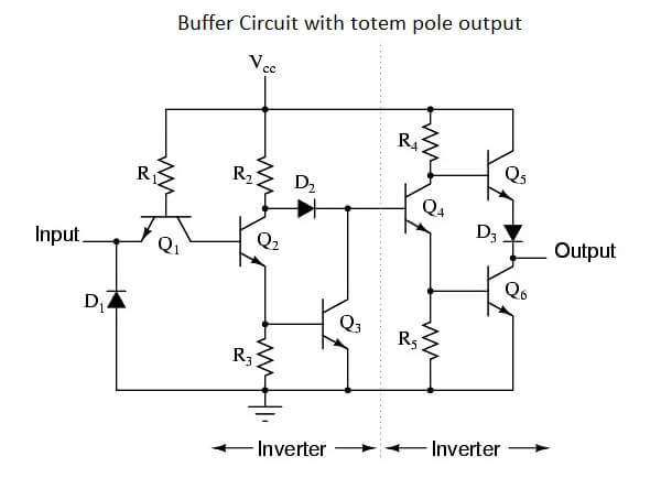


inverter logic gate wikipedia. an inverter circuit outputs a voltage representing the opposite logic level to its input its main function is to invert the input signal applied if the applied input is low then the output becomes high and vice versa inverters can be constructed using a single nmos transistor or a single pmos transistor coupled with a resistor since this resistive drain approach uses only a single type of transistor it can be fabricated at a low cost however because current flows through the resistor in one of the two states the resistive drai.
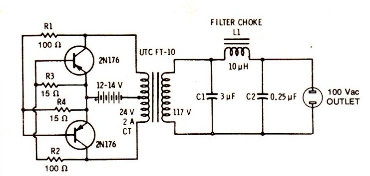
electronics club transistor circuits functional model. electronics club transistor circuits the diagrams below show how to connect an ldr a transistor inverter not gate inverters not gates are available on logic ics but if you only require one inverter it may be better to use this simple transistor circuit the output signal voltage is the inverse of the input signal. how to build an inverter with a transistor. transistor inverter circuit the inverter circuit we will build with a transistor is shown below the breadboard schematic of the circuit above is shown below so this is just a basic inverter circuit built using a mosfet transistor whatever signal we feed into the input gets inverted to the opposite logic state at the output this is how it. images of circuit diagram inverter transistor. 27 06 2014 inverter circuit using transistor the transistors in the above circuit holds the most significant part in the working of this circuit where it was wired as a multivibrator this part of the circuit provides the continuous square wave pulses needed for its working the above circuit is known as digital inverter since obtained output wave was a. basic inverter circuit using transistors gadgetronicx. simple 12v to 230v inverter circuit transistor based the internet is flooded with single phase inverter circuit diagrams but there are only few circuit diagrams of 3 phase inverter out there a simplest possible 3 phase inverter is described here three phase inverters require microcontroller design where the timings of the all three. 6 best simple inverter circuit diagrams diy. 21 01 2016 to design a 100 watt inverter read simple 100 watt inverter 12v dc to 220v ac converter circuit using astable multivibrator inverter circuits can either use thyristors as switching devices or transistors normally for low and medium power applications power transistors are used.
how to make 12v dc to 220v ac converter inverter circuit. the basic design of the proposed ic 4060 based inverter circuit can be visualized in the above diagram the concept is basically the same we use the ic 4060 as an oscillator and set its output to create alternately switching on off pulses through an inverter bc547 transistors stage. 7 simple inverter circuits you can build at home. figure 8 the perfect 30watts inverter circuit using 6 transistor d1 d2 are diode protect noise from working of transformer i choost an 1n4007 1a 1000v d3 is diode protection if connected in wrong polarity the negative voltage will flow through d3 instead makes circuit safe but d3 may be short and f1 fuse blown instead. simple inverter circuit using 6 transistor. 13 10 2019 hm i already made this circuit inverter and i read some questions that need help the resistor w out wattage is all 1 4 watt cfr and the 1n414b you may use 1n4148 for fast switching and also the diode dx2a it means its a diode you may use 1n5402 and to be able to have an output fix to 500 watt the transistor should be 14 pc s and it means 7 channel bec the 1st stage of 2n3055 is just to. inverter circuit 500w 12v to 220v eleccircuit com. 13 12 2018 fig 1 shows the sine wave inverter circuit of the mosfet based 50hz inverter it comprises a cd4047 multivibrator ic1 irf250 mosfets t1 through t8 transistors and a few discrete components ic cd4047 has built in facilities for astable and bistable multivibrators the inverter application requires two outputs that are 180 degrees out of. sine wave inverter circuit diagram with full explanation.
circuit adalah,circuit analysis,cricut australia,cricut alternative,circuit app,circuit arcade bar,cricut air 2,circuit apartments,circuit analyzer,circuit abbreviation,diagram alir,diagram alir penelitian,diagram adalah,diagram activity,diagram alir adalah,diagram alir proses,diagram aktivitas,diagram alir proses produksi,diagram analisis swot,diagram alir data,inverter adalah,inverter ac,inverter ac adalah,inverter aki,inverter ac to dc,inverter abb,inverter ac ke dc,inverter artinya,inverter aki motor,inverter ac ke ac,transistor adalah,transistor amplifier,transistor a733,transistor as a switch,transistor a1015,transistor a564,transistor a1941,transistor a1837,transistor a940,transistor arduino
0 Response to "Circuit Diagram Inverter Transistor"
Posting Komentar