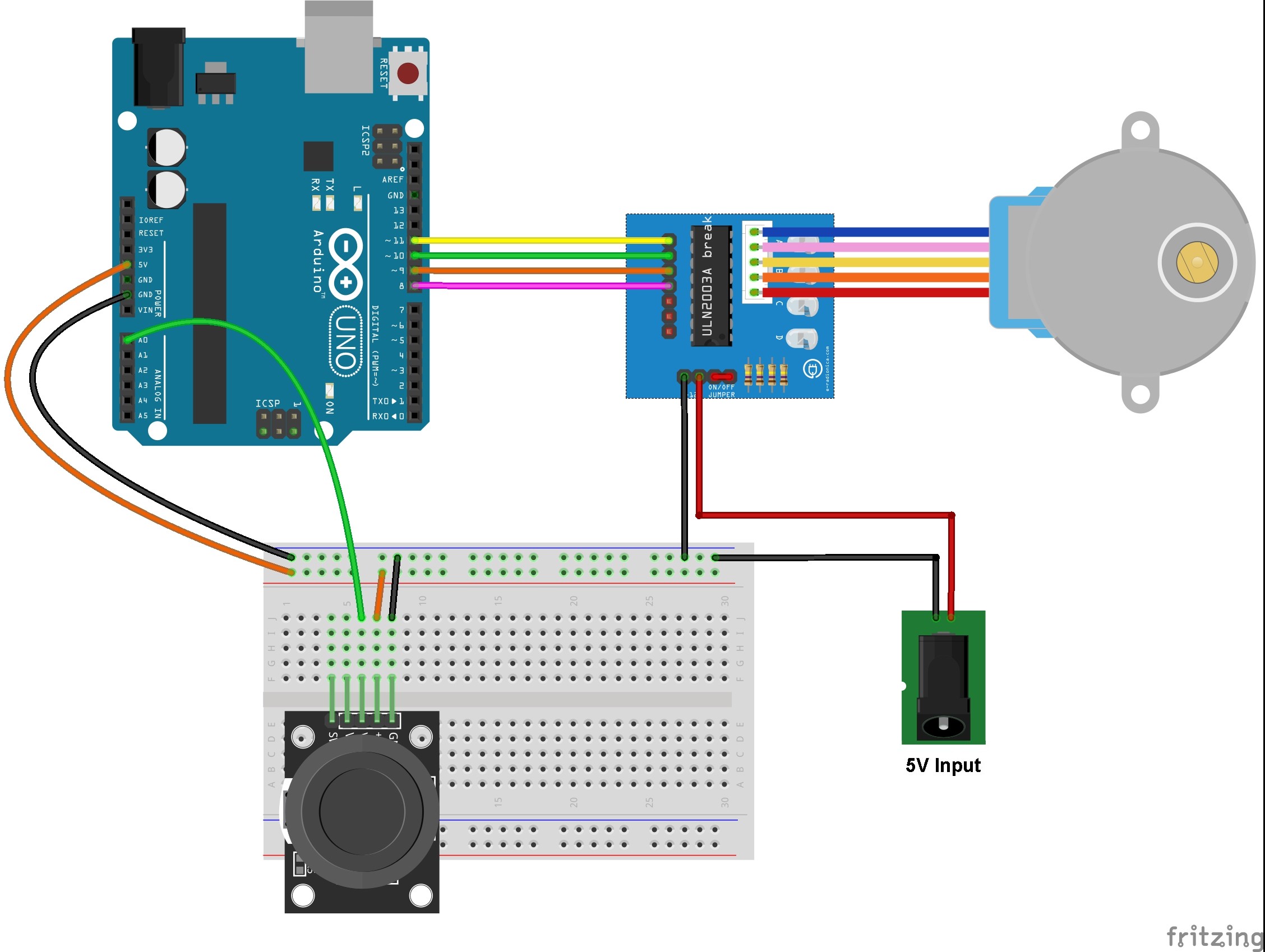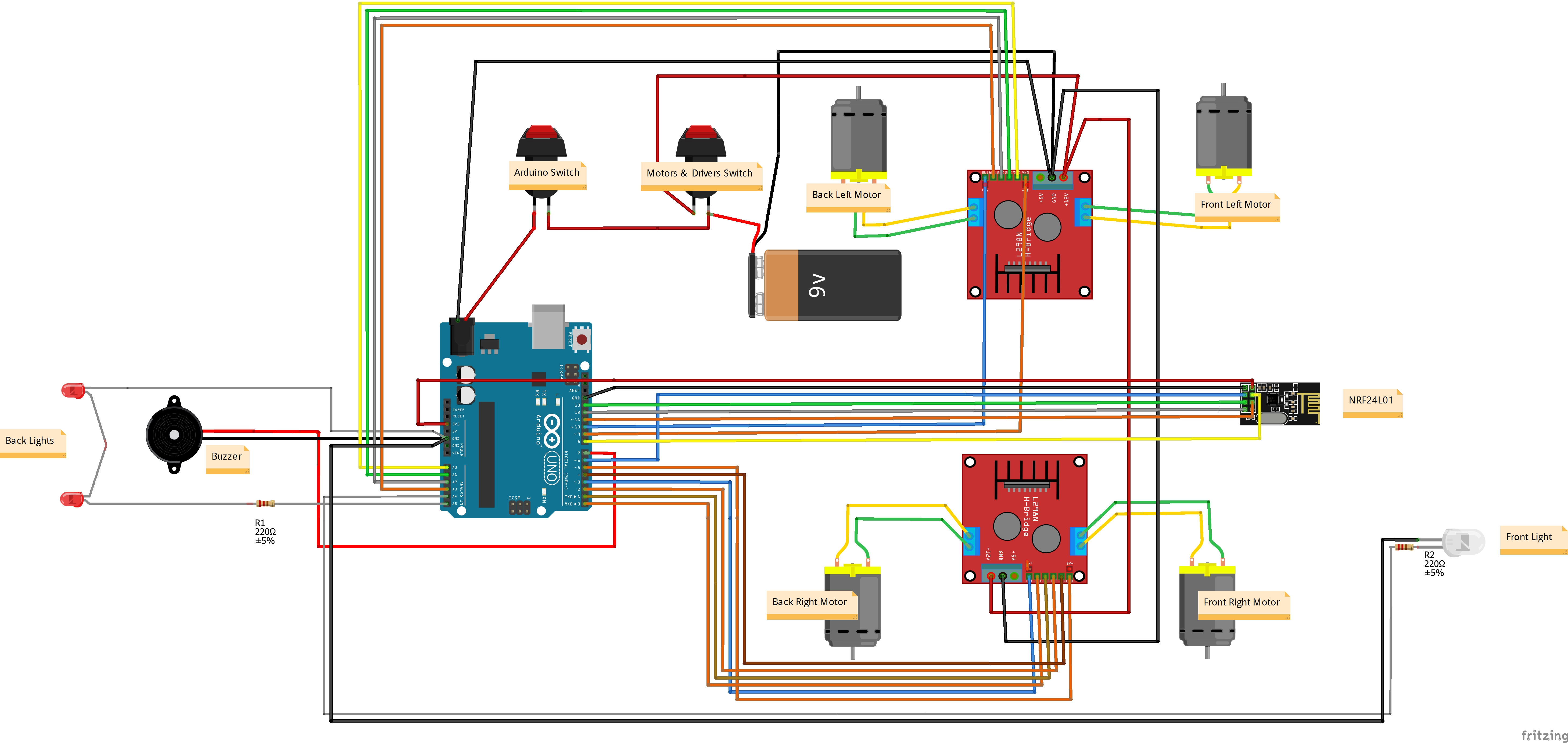


diy joystick game controller using arduino leonardo and. 04 06 2019 so we have four directions of joystick on two adc outputs when the stick is moved the voltage on each pin goes high or low depending on direction circuit diagram this arduino joystick game controller requires connections between the arduino and the joystick as follows code and working explanation.
interfacing joystick with arduino circuitdigest com. 22 03 2018 in this circuit we are interfacing joystick with arduino simply by controlling four leds as per the movement of the joystick we have placed 4 leds in such a way that it represents the direction of the joystick shaft movement this joystick also has a push button which can be used for various other purposes or can be left idle a single led is also attached to the switch of the joystick as. arduino dc motor control with joystick and l293d simple. as shown in the circuit diagram we need only 3 arduino terminal pins a0 analog pin pin 9 and pin 10 pins 9 and 10 are pwm signal outputs at any time there is only 1 active pwm this allows us to control the direction of rotation as well as the speed by varying the duty cycle of the active pwm signal. videos of arduino joystick circuit diagram. here we have interface 1 duel axis joystick with arduino joystick has 2 analogue pins for x axis and y axis and 1 digital pin for switch circuit diagram in the above image you can see we have a4 and a5 of arduino uno for analogue pins of joystick and one switch which is connected to 4th pin of arduino. how to interface dual axis joystick with arduino uno. 12 07 2019 the joystick and all the led s are connected with the arduino as per the circuit diagram now let s discuss the arduino programming arduino joystick library the use of the 2 axis analog joystick with the arduino is really easy and you don t really need a library you can use the x axis and y axis without any problem. 2 axis joystick arduino project joystick button. as long as the module receives the data arduino reads the data and moves the servo motor according to the data circuit diagram 1 the transmitter is connected as follows the hor of the joystick module is connected to arduino s a0 ver to arduino s a1 gnd to arduino s gnd and vcc to arduino.
images of arduino joystick circuit diagram. 18 10 2018 this post shows how to control stepper motor speed and direction of rotation using arduino uno board and ps2 joystick the stepper motor used in this example is 28byj 48 unipolar stepper motor which usually comes with its driver board in the last arduino project i build a simple controller for this stepper motor project link is below. arduino joystick and nrf24l01 control servo motor 2. 05 07 2018 since the joystick is essentially a combination of two potentiometers and a switch of course you can easily guess how to interface it with arduino as you might have already connected a potentiometer with arduino circuit diagram the following image shows a simple connection between arduino uno and the joystick module code. stepper motor control with arduino and joystick simple. in this tutorial we will learn how to interface an analog joystick module with arduino the analog joystick module is similar to two potentiometers connected together one is for vertical movement y axis the other is for horizontal movement x axis. arduino joystick interface control servo using arduino. to get stable readings from the key select pin it needs to be connected to vcc via a pull up resistor the built in resistors on the arduino digital pins can be used for a tutorial on how to activate the pull up resistors for arduino pins configured as inputs see this arduino joystick module demo. analog joystick with arduino tutorial.
arduino joystick module example 42bots com.
arduino adalah,arduino app,arduino atmega,arduino array,arduino adalah pdf,arduino analog input,arduino android,arduino atmega328,arduino analogwrite,arduino atmega 2560,joystick android,joystick adalah,joystick arduino,joystick android apk,joystick arcade,joystick android terbaik,joystick and sliders,joystick apk,joystick android tv,joystick android bluetooth,circuit adalah,circuit analysis,cricut australia,cricut alternative,circuit app,circuit arcade bar,cricut air 2,circuit apartments,circuit analyzer,circuit abbreviation,diagram alir,diagram alir penelitian,diagram adalah,diagram activity,diagram alir adalah,diagram alir proses,diagram aktivitas,diagram alir proses produksi,diagram analisis swot,diagram alir data
0 Response to "Arduino Joystick Circuit Diagram"
Posting Komentar