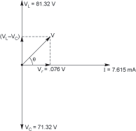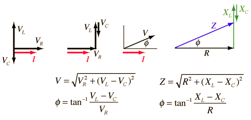


rlc series circuit phasor diagram with solved problem. 27 09 2018 rlc series circuit contains a resistor capacitor and inductor in series combination across an alternating current source the behavior of components can be explained by phasor diagrams impedance and voltage triangles.
series rlc circuit and rlc series circuit analysis. rlc series circuit the rlc series circuit is defined as when a pure resistance of r ohms a pure inductance of l henry and a pure capacitance of c farads are connected together in series combination with each other as all the three elements are connected in series so the current flowing in each element of the circuit will be same as the total current i flowing in the circuit. what is rlc series circuit phasor diagram impedance. phasor diagram of series rlc circuit phasor diagram of inductive series rlc circuit we normally take the direction of the circuit current as the reference axis of the diagram the voltage drop across the resistance will have the same phase as that circuit current the voltage drop across the inductive reactance will be perpendicularly upward. images of rlc series circuit phasor diagram. 30 12 2018 rlc circuit for drawing the phasor diagram of series rlc circuit follow these steps step i in case of series rlc circuit resistor capacitor and inductor are connected in series so the current flowing in all the elements are same i e i r i l i c i for drawing the phasor diagram take current phasor as reference and draw it on horizontal axis as shown in diagram. series rlc circuit impedance with phasor diagram about. 17 09 2017 in this video phasor diagram representation of voltage and current for series rc rl and rlc circuit has been explained and the examples based on this phasor representation has been solved 1. series rlc circuit electrical4u. 08 08 2016 for series rl circuits shows how to draw the voltage and impedance phasor diagrams how to calculate the voltage of the source the phase angle the current through the circuit and the impedance.
phasor diagram of rl rc and rlc circuits with examples. phasor diagram for a parallel rlc circuit however the analysis of parallel rlc circuits is a little more mathematically difficult than for series rlc circuits when it contains two or more current branches so an ac parallel circuit can be easily analysed using the reciprocal of impedance called admittance. rlc circuits 7 of 14 series rl an explanation voltage. this demonstration shows a phasor diagram in an ac series rlc circuit the circuit consists of a resistor with resistance r an inductor with inductance l and a capacitor with capacitance c the current in an rlc series circuit is determined by the differential equation i e 0. parallel rlc circuit and rlc parallel circuit analysis. rc series circuit a circuit that contains pure resistance r ohms connected in series with a pure capacitor of capacitance c farads is known as rc series circuit a sinusoidal voltage is applied to and current i flows through the resistance r and the capacitance c of the circuit the rc series circuit is shown in the figure below. phasor diagram for series rlc circuits wolfram cloud. what is rc series circuit phasor diagram and power curve.
rlc adalah,rlc arus bolak balik,rlc army,rlc architects,rlc aerospace,rlc ac circuit,rlc association,rlc abbreviation,rlc archive,rlc application,series a,series adalah,series a funding,series apple watch,series and parallel circuit,series about doctor,serie a table,series avengers,series a b c funding,series and sequence,circuit adalah,circuit analysis,cricut australia,cricut alternative,circuit app,circuit arcade bar,cricut air 2,circuit apartments,circuit analyzer,circuit abbreviation,phasor adalah,phasor addition,phasor analysis,phasor addition calculator,phasor antenna,phasor addition theorem,phasor arithmetic,phasor addition rule,phasor angle symbol,phasor animation,diagram alir,diagram alir penelitian,diagram adalah,diagram activity,diagram alir adalah,diagram alir proses,diagram aktivitas,diagram alir proses produksi,diagram analisis swot,diagram alir data
0 Response to "Rlc Series Circuit Phasor Diagram"
Posting Komentar