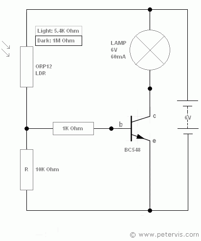


transistor as a switch using ldr peter vis. simple transistor circuits with ldr are very common and utilised in night lighting and emergency lighting systems the transistor may directly drive a low current led or bulb or a relay coil which then acts as a switch to control a high current load.
diy ldr switch circuits electroschematics com. ldrs or light dependent resistors are very useful especially in light dark sensor circuits normally the resistance of an ldr is very high sometimes as high as 1000 000 ohms but when they are illuminated with light resistance drops dramatically ldr switch circuit diagrams this is a light switch or light activated relay circuit. light activated switch circuit using ldr sensor. ldr circuits and projects ldr light dependent resistor and is a key component in various electronic circuits embedded control europe elektroda eeweb ldr circuits projects 23 browse through a total of 23 ldr circuits and projects ldr pole light switch circuit jim keith 12 07 2012 my vintage 62 year old pole light has. images of ldr control switch circuit diagram. 12 01 2018 it seems to me that as your circuit stands at the moment it will only work in daylight so you can create a dark situation by covering the ldr to make the circuit switch and then uncovering the ldr to make it switch again a proximity switch and a motion detector dont care what level the ambient light conditions are. ldr circuits projects electroschematics. this basic light sensor circuit is of a relay output light activated switch a potential divider circuit is formed between the photoresistor ldr and the resistor r1 when no light is present ie in darkness the resistance of the ldr is very high in the megaohms m range so zero base bias is applied to the transistor tr1 and the relay is de energised or off. wireless switch circuit using ldr and cd4017. 16 03 2018 we previously made many circuits using ldr which use ldr to automate the lights according to requirement working of ldr controlled led using arduino as per the circuit diagram we have made a voltage divider circuit using ldr and 100k resistor the voltage divider output is feed to the analog pin of the arduino.
light sensor including photocell and ldr sensor. 01 11 2013 how the ldr circuit diagram works the ldr circuit diagram works like this when it s dark the ldr has high resistance this makes the voltage at the base of the transistor too low to turn the transistor on therefore no current will go from the collector to the emitter of the transistor. arduino light sensor circuit using ldr. ldr circuit diagram build electronic circuits. how to make ldr darkness sensor circuit simple diy 7.
ldr adalah,ldr artinya,ldr arduino,ldr asi,ldr asi adalah,ldr adalah singkatan dari,ldr an,ldr artinya apa,ldr agama,ldr animasi,control android from pc,control adalah,control alt delete,control alt delete windows 7,control activities,control alt delete mac,control android from android,control account,ctrl alt del,control activities coso,switch adalah,switch animal crossing,switch artinya,switch account mobile legend,switch axe,switch account,switch axe build,switch accessories,switch apk,switch android,circuit adalah,circuit analysis,cricut australia,cricut alternative,circuit app,circuit arcade bar,cricut air 2,circuit apartments,circuit analyzer,circuit abbreviation,diagram alir,diagram alir penelitian,diagram adalah,diagram activity,diagram alir adalah,diagram alir proses,diagram aktivitas,diagram alir proses produksi,diagram analisis swot,diagram alir data

0 Response to "Ldr Control Switch Circuit Diagram"
Posting Komentar