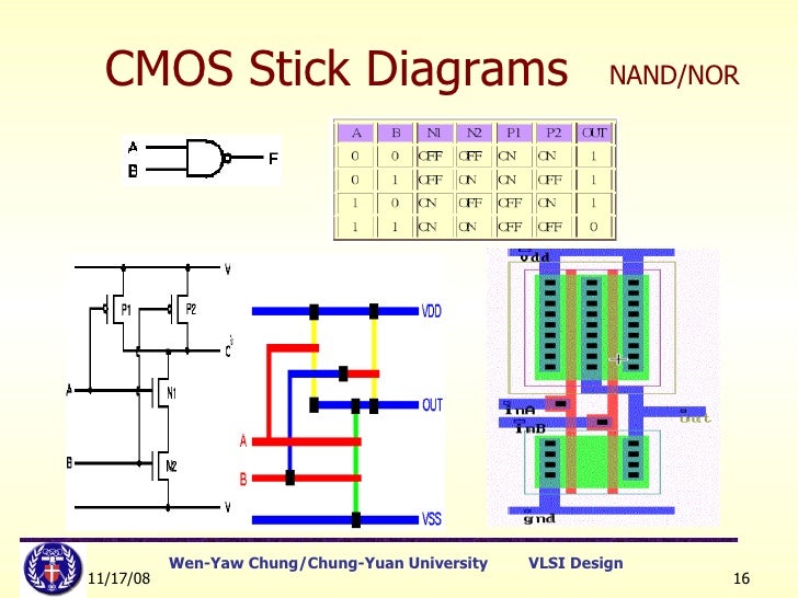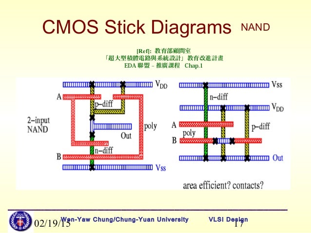


nand and nor gate using cmos technology vlsifacts. 04 08 2015 a basic cmos structure of any 2 input logic gate can be drawn as follows 2 input nand gate truth table circuit the above drawn circuit is a 2 input cmos nand gate now let s understand how this circuit will behave like a nand gate the circuit output should follow the same pattern as in the truth table for different input combinations.
cmos gate circuitry logic gates electronics textbook. nand gates are basic logic gates and as such they are recognised in ttl and cmos ics the standard 4000 series cmos ic is the 4011 which includes four independent two input nand gates these devices are available from most semiconductor manufacturers such as fairchild semiconductor philips or texas instruments these are usually available in both through hole dil and soic format datasheets are readily available in most datasheet databases. nand gate wikipedia. shown on the right is a circuit diagram of a nand gate in cmos logic if both of the a and b inputs are high then both the nmos transistors bottom half of the diagram will conduct neither of the pmos transistors top half will conduct and a conductive path will be established between the output and v ss ground bringing the output low. images of cmos nand gate circuit diagram. 08 06 2012 the logic and and or are reviewed the nand and nor symbols are explained the nand gate and nor gate is constructed using cmos mosfet transistors the set reset latch is presented using both. cmos wikipedia. 27 01 2018 for the love of physics walter lewin may 16 2011 duration 1 01 26 lectures by walter lewin they will make you physics recommended for you. the cmos nand and nor gate youtube. 25 08 2015 so if any one or both inputs are low the output of nand gate will be high in this nand gate circuit diagram we are going to pull down both input of a gate to ground through a 1k resistor and then the inputs are connected to power through a button so when the button is pressed the corresponding pin of gate goes high.
cmos nand gate youtube. nand gates can also be used to produce any other type of logic gate function and in practice the nand gate forms the basis of most practical logic circuits by connecting them together in various combinations the three basic gate types of and or and not function can be formed using only nand gates for example. nand gate circuit diagram and working explanation. practical circuits using nand gates here we will use the very versatile ic 4093 which is comprised of 4 nand gates schmitt trigger and see how we can wire them up into a few amazing yet simple circuits oscillator you will need just a resistor and a capacitor to build an oscillator from these gates as shown in the figure the. logic nand gate tutorial with nand gate truth table. generic static cmos gate v dd v pullup network connects output to dd contains only pmos in1 v in out 2 inn pulldown network nand gate b a a b nearly all transistors in digital cmos circuits. nand gate circuit designs you can build flasher set. cmos technology and logic gates mit opencourseware.
cmos adalah,cmos and gate,cmos acronym,cmos abbreviation,cmos analog circuit design,cmos amplifier,cmos applications,cmos advantages,cmos and,cmos and ttl,nand adalah,nand and nor gates,nand and nor implementation,nand as or gate,nand as xor gate,nand as and gate,nand acronym,nand and nor flash,nand and dram,nand as or,gate anime,gate adalah,gate artinya,gate away,gate anime season 3,gate acara,gate airasia,gate aster,gate a moi,gate admin,circuit adalah,circuit analysis,cricut australia,cricut alternative,circuit app,circuit arcade bar,cricut air 2,circuit apartments,circuit analyzer,circuit abbreviation,diagram alir,diagram alir penelitian,diagram adalah,diagram activity,diagram alir adalah,diagram alir proses,diagram aktivitas,diagram alir proses produksi,diagram analisis swot,diagram alir data
0 Response to "Cmos Nand Gate Circuit Diagram"
Posting Komentar