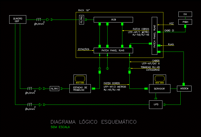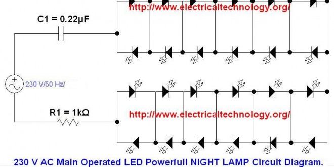


ups uninterruptible power supply circuit diagram. ups uninterruptible power supply is a device used for protection against over voltage under voltage provide continuous supply in case of supply outage protection against voltage spikes frequency fluctuation and against distortion in voltage wave form.
uninterruptible power supply ups basic circuit diagram. the circuit drawn pertains to a regular industrial ups uninterruptible power supply which shows how the batteries take control during an outage in electrical supply or variation beyond the normal limits of the voltage line without disruption on the operation providing a steady regulated output 5 volts by lm7805 and an unregulated supply 12 volts. automatic ups inverter wiring connection diagram to. related electrical wiring tutorial ups inverter wiring diagram with auto manual changeover switch system now according to the below ups connection diagram connect an extra wire phase to those appliances where we have already connected phase and neutral wires from power house db i e two wire as phase live as shown in the below fig. images of electrical ups diagram. uninterrupted power supply circuit diagram types of ups electrical power supply intrusions can come in a different forms like surges voltage dips voltage spikes and harmonics these troubles can cause serious damage to electrical gears mostly during the production stages or. types of uninterruptible power supply devices with working. 17 12 2019 an uninterruptible power supply ups is defined as a piece of electrical equipment which can be used as an immediate power source to the connected load when there is any failure in the main input power source in a ups the energy is generally stored in flywheels batteries or super. uninterruptible power supply ups electrical4u. ups inverter wiring diagrams connection how to connect automatic ups inverter to the home supply system a complete note on solar panel installation calculation about no of solar panels batteries rating backup time inverter ups rating load and required watts with circuit diagrams.
ups inverter wiring diagrams connection. ups block diagram in this article we will discuss the online ups block diagram and offline ups block diagram ups stands for uninterruptible power supply ups is used with the electronic devices which are required to keep on for sometime when the main power supply is suddenly off. explained offline and online ups block diagram etechnog. 25 09 2019 small ups 6v backup this power supply circuit system consists of a transformer a bridge rectifier and an electrolytic capacitor and there is a zener diode for controller the output power transistor bd135 npn of this circuit and will be determined at a constant voltage of 7 5 volts. simple ups circuit diagram eleccircuit com. schneider electric easy ups line interactive sinewave smvs is a versatile uninterruptable power supply developed to handle a wide voltage range in regions with inconsistent power conditions while also delivering quality millions of professionals trust around the world. uninterruptible power supply ups schneider electric. an uninterruptible power supply or uninterruptible power source ups is an electrical apparatus that provides emergency power to a load when the input power source or mains power fails a ups differs from an auxiliary or emergency power system or standby generator in that it will provide near instantaneous protection from input power interruptions by supplying energy stored in batteries. uninterruptible power supply wikipedia.


0 Response to "Electrical Ups Diagram"
Posting Komentar